
What Is an RMU Electrical Panel and How Does It Work?

An Rmu Electrical Panel is a compact medium-voltage assembly used to connect, protect, and isolate sections of a distribution network. It often serves ring-shaped networks, where power can reach a site from more than one direction. Inside the metal enclosure, operators may find load-break switches, circuit breakers, fuses, busbars, and earthing switches. The exact arrangement varies. Some units use gas insulation; others use solid insulation or air-based designs. It is not one universal box.

Electrical engineer and safety author John Cadick’s guidance can be paraphrased this way: “Reliable switching depends on understanding equipment limits, condition, and operating steps.” This is a paraphrase, not a verbatim quotation. That distinction matters when technical claims need checking. In operation, a switch directs or interrupts current, while protective devices help clear faults. Interlocks can prevent certain unsafe switching sequences, but they do not replace training or careful procedures. A technician may inspect position indicators, labels, and cable terminations before work begins. Small details matter. A misleading indicator or unclear diagram can complicate an otherwise routine task. This introduction will explain the panel’s main components, how current moves through it, and where protection fits. It will also note what a basic overview cannot establish: the correct operating steps depend on the specific model, site design, and manufacturer’s documentation.
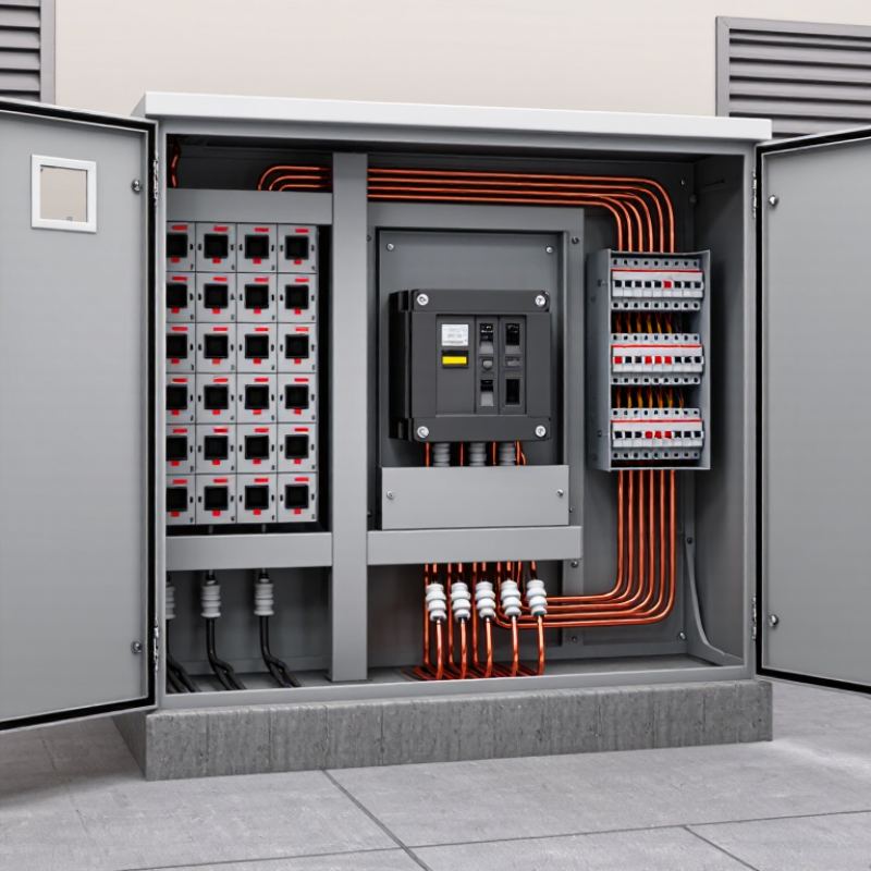
What Is an RMU Electrical Panel and How Does It Work?

What an RMU Electrical Panel Is and Where It Fits in a Power Network

An RMU, or ring main unit, is compact medium-voltage switchgear used in local electricity distribution. It sits between a primary substation and distribution transformers, often inside a street-side cabinet or a building’s electrical room. It is not a transformer. Its job is to switch, protect, and isolate sections of the network. A typical unit combines incoming and outgoing feeder switches with a transformer-protection switch or circuit breaker. The exact arrangement depends on the network design and utility requirements.

In a ring network, power can reach a local substation from either direction. If a cable section develops a fault, operators can isolate it and restore supply through another route, where the network allows. The practical value of the RMU is that it helps manage a small, defined point in a much larger system.

The International Energy Agency’s 2023 report, Electricity Grids and Secure Energy Transitions, says annual grid investment must rise to more than $600 billion by 2030, from about $300 billion today. This figure covers grids broadly, not RMUs alone.

Real sites are less tidy than diagrams suggest. Space, fault levels, maintenance access, and future load all affect equipment selection. A compact unit may save room, but it does not remove the need for sound protection coordination.

The Main Components Inside an RMU

Inside an RMU, the busbar links incoming and outgoing circuits through a compact, enclosed assembly. A load-break switch opens or closes normal load current; an earthing switch grounds an isolated section for maintenance. Some configurations add fuses, while others use a circuit breaker with protective relays. Current and voltage transformers can provide measurement signals. These parts sit within an air-insulated or sealed gas-insulated enclosure, depending on the design. Small parts matter. Interlocks help prevent unsafe operating sequences, and pressure-relief features manage internal faults. The exact arrangement varies, so a single diagram should never be treated as a universal layout.

The IEA’s 2023 report, Electricity Grids and Secure Energy Transitions, estimates that 80 million kilometres of electricity grids must be added or refurbished by 2040 to meet global needs.

That expansion makes compact distribution equipment increasingly relevant, but reliable operation still depends on correct selection and inspection. Check relay settings, contact condition, and earthing-switch operation against the equipment documentation. A panel can look straightforward from the outside. Inside, the protection logic may be less obvious than expected. I’ve found that clear component labels and current drawings are easy to overlook, yet they make maintenance safer and fault diagnosis faster.

How Power Flows Through an RMU

In a typical RMU, incoming medium-voltage power enters through one ring switch and reaches a shared busbar. From there, it can continue through the outgoing ring switch or branch through a transformer feeder. That feeder may use a switch-fuse arrangement or a circuit breaker, depending on the equipment design. Not always. Some ring networks operate with a normally open point, so power reaches a section from one direction until operators reconfigure the circuit.

If a cable fault occurs, protection and operating procedures help isolate the affected section. The switches on either side can then be opened, while healthy sections may receive power from the other direction if the network design allows it. The sequence matters: switching must follow site procedures and the RMU’s ratings. The International Energy Agency’s 2023 report, Electricity Grids and Secure Energy Transitions, says annual grid investment needs to rise from about $300 billion to more than $600 billion by 2030. As networks expand, reliable switching and clear feeder layouts become increasingly important.

Tip: Check the single-line diagram before switching. Confirm feeder labels, the normal open point, and the approved operating sequence; drawings can be outdated, so verify them on site.

How Switching and Fault Protection Work

An RMU controls medium-voltage circuits at a local distribution point. Its switches let operators connect, disconnect, or isolate sections of a network. During normal operation, a load-break switch can open or close a circuit carrying ordinary load current. The switching action happens inside an enclosed, insulated compartment, limiting exposure to live parts. That enclosure matters.

Fault protection depends on the RMU’s design. Some units use fuses, while others use a circuit breaker and protective relay. A relay monitors electrical conditions through sensors, such as current transformers. If it detects a fault current, it signals the breaker to open and disconnect the affected section. With a fuse-based unit, excessive current melts the fuse element and interrupts the circuit. The response helps prevent damage from spreading, though it cannot remove every risk.

Operators can isolate a cable section and, where fitted, use an earth switch to ground it before maintenance. Mechanical or electrical interlocks help prevent unsafe switching sequences. Small detail, big consequence. Actual arrangements vary by network and equipment rating, so the unit’s diagrams and operating instructions matter more than assumptions. Switching and testing should be handled by qualified personnel using the site’s approved procedures. Even a clear position indicator deserves verification.

What Is an RMU Electrical Panel and How Does It Work? — How Switching and Fault Protection Work

Component or Function Typical Arrangement Normal Operation Switching or Fault Response Important Practical Note
Ring Main Unit (RMU) A compact medium-voltage switchgear assembly used at a distribution point, commonly with two ring-line ways and one transformer feeder way. Connects a transformer or local distribution load to a medium-voltage network. Allows selected circuits to be isolated or switched while other network sections may remain in service, depending on network layout and operating procedures. “RMU” describes a type of distribution switchgear, not one fixed circuit design. Voltage rating, configuration, and protection vary by installation.
Ring-line ways Usually two switch-disconnector ways connect the unit to the incoming and outgoing sections of a ring network. Carry the network current through the distribution point. A load-break switch can open or close normal load current within its rated limits. It is not generally intended to interrupt short-circuit current. A ring network can provide an alternative supply route, but continuity depends on the network arrangement and switching plan.
Transformer feeder way Often uses a circuit breaker with protective relays, or a switch-fuse combination, to connect a distribution transformer. Supplies the transformer and its downstream low-voltage loads. A circuit breaker trips on a protection command; in a switch-fuse arrangement, suitable fuses interrupt specified fault currents. The correct protection arrangement depends on transformer size, fault levels, coordination requirements, and local standards.
Switch-disconnector Installed in one or more circuit ways and rated for defined switching duties. Provides a means to connect or disconnect a circuit under specified operating conditions. Opens normal load current within its rating and may be used to isolate a section after the circuit has been safely de-energized. Do not treat a load-break switch as a fault-current circuit breaker unless the equipment is specifically rated for that duty.
Circuit breaker and protection relay Commonly fitted on a transformer feeder where relay-based protection is required. The breaker remains closed while the circuit operates within its normal limits. When relay measurements indicate a fault condition, the relay sends a trip command to the breaker, which interrupts current within its rated breaking capacity. Protection settings and coordination should be selected and verified by qualified personnel for the actual network.
Switch-fuse protection A switch-disconnector combined with appropriately rated high-voltage fuses may protect a transformer feeder. The switch controls the feeder during permitted switching operations; the fuses remain in series with the circuit. A fuse melts and interrupts current when its operating characteristics and the fault current fall within its specified range. Fuse selection and coordination are essential. A fuse is not a substitute for every type of circuit-breaker protection.
Earth switch Provided on selected ways to connect an isolated circuit section to earth. Normally remains open while the circuit is in service. After the circuit is isolated and absence of voltage is verified using the approved procedure, the earth switch can help discharge and earth the section for work. Operating sequence and safety verification must follow the equipment instructions and site rules.
Interlocks and position indication Mechanical or electrical interlocks and indicators are commonly provided for switching and earthing operations. Show or control the permitted operating sequence for connected, isolated, and earthed positions. Interlocks are designed to prevent specified unsafe operations, such as closing an earth switch onto an energized circuit. Interlocks reduce risk but do not replace training, isolation procedures, voltage testing, or other safety controls.
Insulation and enclosure Switchgear may use gas insulation, solid insulation, or other designs within a metal enclosure. Provides insulation and protection for live medium-voltage components. Enclosure design helps contain and separate components; internal fault performance depends on the equipment’s tested design and rating. Insulation medium, maintenance needs, environmental limits, and end-of-life handling differ between designs.
Voltage indication and testing points Voltage presence indicators or approved test interfaces may be fitted to relevant circuit ways. Provide an indication of voltage status or allow use of a compatible voltage-detection device. Support verification steps before earthing or maintenance, when used according to the manufacturer’s instructions and site procedure. An indicator should not be assumed to prove a circuit is safe to touch; use the approved test-for-dead process.
Typical RMU features and operating principles are shown for general information. Actual equipment ratings, switching duties, protection, and safety procedures depend on the specific installation.

Common RMU Types, Applications, and Maintenance Needs

What Is an RMU Electrical Panel and How Does It Work?

RMUs are compact medium-voltage switchgear assemblies. Common designs include air-insulated, gas-insulated, and solid-insulated units. Their switching arrangements may serve ring networks or radial feeders. They isolate faults and redirect supply, helping crews maintain service to unaffected sections. You’ll find them in building basements, roadside cabinets, and utility substations. Compact does not mean simple.

Applications are growing alongside grid expansion. The IEA’s 2023 report, Electricity Grids and Secure Energy Transitions, says annual grid investment needs to rise from about $300 billion to more than $600 billion by 2030. That figure covers grids broadly, not RMUs alone. Still, it highlights why dependable distribution equipment matters. Maintenance varies by design and site conditions. Teams typically check enclosure condition, cable terminations, operating mechanisms, interlocks, and protection settings. For gas-insulated units, inspect pressure indicators where fitted. Follow the equipment’s maintenance schedule; dust, moisture, and frequent switching can change what needs attention. Small oversights matter.

Tips: Keep inspection records, verify safe isolation before work, and investigate unusual heat, noise, or odors promptly. A clean cabinet is useful, but it does not prove the internals are healthy.

What Is an RMU Electrical Panel and How Does It Work?

Typical RMU feeder configurations

A ring main unit (RMU) is medium-voltage switchgear used to connect sections of a distribution network and supply a transformer. These examples show the number of ring feeder ways and transformer feeder ways in common configurations. Actual designs vary by network and installation.

Go to Top